cpu:s5pv210
touch ic :FT5406
平台:android
1. 首先,分析下 FT5406 的基本电路接口:
基本都是通用的接口,如 I2C 接口,INT,WAKE,RST。如图:
以上可知,我们在驱动中必须定义一个中断口,来启动接收触摸数据,一个gpio脚来复位FT5406。
wake:主要靠cpu发送一个唤醒指令给FT5406。
#define pin_irq S5PV210_GPH0(1)
#define pin_rst S5PV210_GPB(1)
2. 再次,需确认FT5406的从地址,以便于I2C访问得到。这个可以根据FT5406数据手册查找到.
可知从地址高位必须为:3,低位必须根据i2ccon设定的值来确定,这点很奇怪。
我这边找到的从地址为:0x38
3. 基本的东西确认好后,剩下的就是根据FT5406数据手册上的指令,开始写驱动了。
在此之前,我们先了解下驱动如何实现电容屏的多点触摸,其实很简单,主要需要
触摸屏IC FT5406 能够捕获多点数据,这点电容屏基本多能支持到捕获2点以上,而
FT5406 可以捕获5个触摸点,编写驱动时,只要去获取这几个点的数据,然后上报
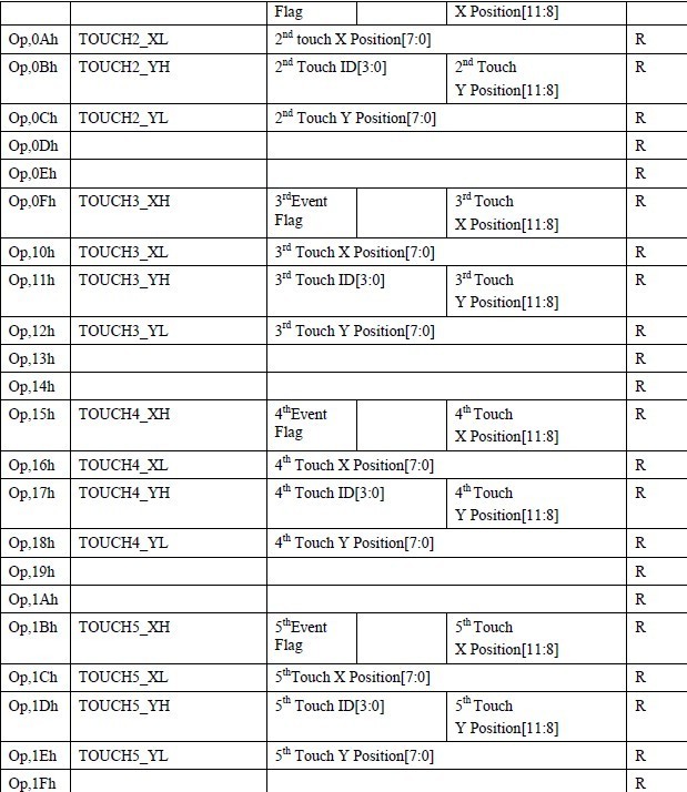
就行。格式如图:
解释:
02h : 捕获的触摸点个数
03h- 1eh :对应每个点的x,y坐标数值。
———————————————————————————————————————————————-
首先配置i2c_board_info,把从地址提供过去。
<
p style=”text-align:left;” class=”MsoNormal” align=”left”>
//arch/arm/mach-s5pv210/mach-smdk110.c

//i2c_board_info用于构建信息表来列出存在的I2C设备。这一信息用于增长新型I2C驱动的驱动模型树。对于主板,它使用i2c_register_board_info()来静态创建。对于子板,利用已知的适配器使用i2c_new_device()动态创建。
//I2C设备创建模板
struct i2c_board_info {
char type[I2C_NAME_SIZE]; //芯片类型,用于初始化i2c_client.name
unsigned short flags; //用于初始化i2c_client.flags
unsigned short addr; //存储于i2c_client.addr
void *platform_data; //存储于i2c_client.dev.platform_data

struct dev_archdata *archdata; //拷贝至i2c_client.dev.archdata
int irq; //存储于i2c_client.irq
};

static struct i2c_board_info i2c_devs0[] __initdata = {
#ifdef CONFIG_TOUCHSCREEN_CDTLCD
{
I2C_BOARD_INFO("ft5x0x_ts", 0x38),
.irq = IRQ_EINT1,
},
#endif
};


//使用Linux I2C驱动栈,系统可以在初始化时宣告板载信息表。这些应该在靠近arch_initcall()时的板子相关的初始化代码或同等情况时,在I2C适配器驱动被注册之前被执行。例如,主板初始化代码可以定义几个设备,也可以在叠板的每个子板初始化代码中定义。
//I2C设备会在相关的总线适配器被注册后创建。此后,标准驱动模型工具通常绑定新型I2C驱动至I2C设备。对于使用这一函数宣告的设备,在动态分配的情况下总线号是不可用的。
//传递的板子信息可以安全的是__initdata,但是由于不能拷贝,要小心嵌入式指针(如platform_data,functions等)
//静态的宣告I2C设备
int i2c_register_board_info(int busnum, struct i2c_board_info const *info, unsigned len);
@busnum:指定这些设备属于哪个总线
@info: I2C设备描述符向量
@len:向量中描述符的数量;为了预留特定的总线号,可以是0。


i2c_register_board_info(0, i2c_devs0, ARRAY_SIZE(i2c_devs0));


在你对应的machine配置里会执行“i2c_register_board_info”一个函数,它会将一个i2c_board_info的结构体注册进系统,

可以发现,在目录/sys/bus/i2c/devices下的设备就是这个i2c_board_info结构体里所描述的I2C设备,


而/sys/bus/i2c/devices下的设备名字就是根据i2c_board_info结构体中定义的I2C Address来命名的。


所以添加一个I2C设备时,除了需要编写这个I2C设备的驱动之外,还需要在machine里面加入I2C设备的i2c_board_info内容。

-----------------------------------------------------------------------------------------------------------------------------------------

下面的是驱动的入口函数cdtlcd_ft5406_ts_init(),分几部分来讲解分析:

static int __init cdtlcd_ft5406_ts_init(void)
{
int ret=0;
printk(FT5406_DEBUG_LEVEL "%s
", __func__);
ret = cdtlcd_i2c_init_hw(); //初始化irq,rst
....

}


// 具体实现
static int cdtlcd_i2c_init_hw(void)
{
int error =0;
//init rst pin
error = gpio_request(pin_rst, "cdtlcd_gpio_rst");
if(error 0){
gpio_free(pin_rst);
printk(KERN_INFO "request pin_rst error
");
return error;
}
s3c_gpio_cfgpin(pin_rst, S3C_GPIO_OUTPUT);
s3c_gpio_setpull(pin_rst,S3C_GPIO_PULL_UP);
gpio_set_value(pin_rst,1);
// init int pin
error = gpio_request(pin_irq,"cdtlcd_gpio_int");
if(error 0){
gpio_free(pin_irq);
printk(KERN_INFO "request pin_irq error
");
return error;
}
s3c_gpio_setpull(pin_irq, S3C_GPIO_PULL_NONE);
s3c_gpio_cfgpin(pin_irq, 0xf);//int
printk(KERN_INFO " hw init success!
");
return error;

}


接下来,初始化devi2c这两个结构,向这两个结构赋值0

通过函数init_MUTEX(i2c.wr_sem1)结构来初始化信号量,因为在2.6.37版本以上的内核代码提供了这个函数来支持信号量的初始化,其实我们如果看一下这个函数的原型,可以在include/linux/Semaphore.h头文件中看到如下的原型:

#define init_MUTEX(sem) sema_init(sem 1)

也就是这个信号量的初始化其实调用了sema_init(sem1);这个函数。在初始化完信号量之后,还要通过 i2c.wr_sem.count = 1;来将i2c结构中的信号量进行读写使能。


// init global variable
memset(dev, 0, sizeof(struct dev_data));
memset(i2c, 0, sizeof(struct i2c_data));

//init mutex object
#if LINUX_VERSION_CODE KERNEL_VERSION(2, 6, 37)
init_MUTEX(i2c.wr_sem);
#else
sema_init(i2c.wr_sem,1);
#endif
i2c.wr_sem.count = 1;
<p align="left">
    <br />
第2部分:cdtlcd_i2c_register_device注册i2c设备,这个是重点注册函数,这个函数的调用是整个驱动加载阶段最重要的一个函数,它涉及到后面的i2c驱动的注册,申请和input子系统的注册及中断程序的初始化等等工作。
<div align="left"></p>
//register i2c device
ret = cdtlcd_i2c_register_device();
if(ret 0){
printk(FT5406_ERROR_LEVEL "%s, init hw error
",__func__);
return ret;
}

具体实现:

//register i2c device
static int cdtlcd_i2c_register_device(void)
{

int ret = i2c_add_driver(cdtlcd_i2c_driver); //为i2c总线添加驱动程序方法

if(ret == 0)
{
i2c.valid_i2c_register =1; //标志添加i2c驱动方法成功

printk(FT5406_DEBUG_LEVEL "%s, add i2c device, success
",__func__);
if(i2c.client == NULL)
{
printk(FT5406_ERROR_LEVEL "%s, no i2c board information
",__func__);
return -1;
}
printk(FT5406_DEBUG_LEVEL "%s, client.addr: 0x%X
", __func__, (unsigned int)i2c.client-addr);
printk(FT5406_DEBUG_LEVEL "%s, client.adapter: 0x%X
", __func__, (unsigned int)i2c.client-adapter);
printk(FT5406_DEBUG_LEVEL "%s, client.driver: 0x%X
", __func__, (unsigned int)i2c.client-driver);
if((i2c.client-addr == 0) || (i2c.client-adapter == 0) || (i2c.client-driver == 0)){
printk(FT5406_ERROR_LEVEL "%s, invalid register
", __func__);
return ret;
}
//获取触摸屏IC的参数,如ID,并初始化ft5406寄存器。
cdtlcd_i2c_read_tp_info();
//注册输入子系统
cdtlcd_register_input_device();
//register char device
cdtlcd_register_char_device();

}
else{
printk(FT5406_ERROR_LEVEL "%s, add i2c device, error
", __func__);
return ret;
}
return 0;
}
</div>
<p align="left">
    <br />
</p>
<p style="text-align:left;" class="MsoNormal" align="left">
    <br />
</p>
<p style="text-align:left;" class="MsoNormal" align="left">
    <br />
</p>
<p style="text-align:left;" class="MsoNormal" align="left">
    第一步:先来分析下i2c设备驱动
</p>
<p style="text-align:left;" class="MsoNormal" align="left">
    <div align="left">
// declare i2c function table
static struct i2c_driver cdtlcd_i2c_driver = {
.id_table = cdtlcd_i2c_id, //设备ID,
.driver = {.name = FT5406_NAME,
.owner = THIS_MODULE,
},
//.resume = cdtlcd_i2c_resume, //i2c设备唤醒函数,adnroid中有改动,这里不使用
//.suspend = cdtlcd_i2c_suspend, //i2c使能阻塞函数,adnroid中有改动,这里不使用

.shutdown = cdtlcd_i2c_shutdown, //i2c关闭函数

.probe = cdtlcd_i2c_probe, //在i2c设备被检测到的时候进入该函数

.remove = __devexit_p(cdtlcd_i2c_remove),//注销i2c设备函数
};

static const struct i2c_device_id cdtlcd_i2c_id[] = {
{ FT5406_NAME, 0 },{ }
};
    </div>
    <p align="left">
        <br />
    </p>
    <p style="text-align:left;" class="MsoNormal" align="left">
        我们一个一个的分析这些函数:
    </p>
    <p style="text-align:left;" class="MsoNormal" align="left">
        我们先分析cdtlcd_i2c_probe()函数,这个函数在驱动程序能够在加载时或者在热插拔下检测到设备是调用的第一个函数:
    </p>
    <div align="left">
static int cdtlcd_i2c_probe(struct i2c_client *client, const struct i2c_device_id *id)
{
/*在一个client尝试访问I2C适配器之前,或者在测试适配器是否支持某一设备之前,应当首先检测所需的functionality是否支持*/
if(!i2c_check_functionality(client-adapter, I2C_FUNC_I2C)){
printk(FT5406_DEBUG_LEVEL "%s, I2C_FUNC_I2C not support
", __func__);
return -1;
}
/*当检测到的adapter支持这个设备时,将client赋值到i2c.client中,这样board中的地址和irq就可以获取到了*/


i2c.client = client;
printk(FT5406_DEBUG_LEVEL "%s, i2c new style format
", __func__);
printk("%s, IRQ: 0x%X
", __func__, client-irq);
return 0;
}
    </div>
    <p style="text-align:left;" class="MsoNormal" align="left">
        <br />
    </p>
    <p style="text-align:left;" class="MsoNormal" align="left">
        <br />
    </p>
    <p style="text-align:left;" class="MsoNormal" align="left">
        函数:cdtlcd_i2c_remove():
    </p>
    <p style="text-align:left;" class="MsoNormal" align="left">
static int cdtlcd_i2c_remove(struct i2c_client *client)
{
printk(FT5406_DEBUG_LEVEL "%s
", __func__);
free_irq(client-irq, i2c);
destroy_workqueue(i2c.irq_work_queue);
input_unregister_device(i2c.input_dev);
return 0;
}


函数:cdtlcd_i2c_shutdown()

static void cdtlcd_i2c_shutdown(struct i2c_client *client)
{
printk(FT5406_DEBUG_LEVEL "%s
", __func__);
}

-------------------------------------------------------------------------------------------------------------------------------------

第2步,读取触摸信息,并初始化:

// read tp info
static int cdtlcd_i2c_read_tp_info(void)
{
int rom_value,ret;
unsigned char buf[8]={0};
ret = cdtlcd_read_reg(FT5X0X_REG_FIRMID,buf); //读取 0xa5的固件ID
if(ret 0){
return -1;
}
printk(FT5406_DEBUG_LEVEL "%s , firmware version[%0x h]: 0x%0x
",__func__,FT5X0X_REG_FIRMID,buf[0]);

ret = cdtlcd_read_reg(FT5X0X_REG_FT5201ID,buf); //读取ft5406的 ID
if(ret 0){
return -1;
}
printk(FT5406_DEBUG_LEVEL "%s , FT5201ID[%0x h]: 0x%0x
",__func__,FT5X0X_REG_FT5201ID,buf[0]);

cdtlcd_set_reg(FT5X0X_REG_PMODE,PMODE_ACTIVE); //设置 0x00h = 0x00,为正常模式
cdtlcd_read_reg(FT5X0X_REG_PMODE,buf);
printk("FT5X0X_REG_PMODE=0x%x
",buf[0]);

cdtlcd_read_reg(0x80,buf); //读取ft5406的灵敏度,此IC支持的触摸屏,触摸没反应基本需要调此参数。
rom_value = buf[0];
printk("read 0x80=0x%x
",buf[0]);
cdtlcd_read_reg(0x88,buf); //上报频率,如何触摸感应太慢,可调节此地址。
printk("read 0x88=0x%x
",buf[0]);
{
printk("write para to reg
");
cdtlcd_set_reg(0x80,0x10); //设置 80h 值,s5pv210支持时,数值应小于0x3f,太大了触摸没反应
cdtlcd_set_reg(0x88,0x9);
cdtlcd_read_reg(0x80,buf);
printk("read 0x80=0x%x
",buf[0]);
cdtlcd_read_reg(0x88,buf);
printk("read 0x88=0x%x
",buf[0]);
}
i2c.event.touch_point = TOUCH_POINT;
i2c.event.pressure = PRESS_MAX;
printk(FT5406_DEBUG_LEVEL "%s, max_tp: %d, max_btn: %d
", __func__,SCREEN_MAX_X ,SCREEN_MAX_Y );
return ret;
}

第3步:注册输入子系统
在linux系统中,一般的输入,如:鼠标,键盘,触摸屏等事件类型的输入,都是使用2.6内核的input子系统机制来进行内核与用户空间的数据交互。

// register input device
static int cdtlcd_register_input_device(void)
{
int ret ,key;
i2c.input_dev = input_allocate_device(); //为input子系统设备分配内存,即进行设备名的创建

if(i2c.input_dev == NULL){
printk(FT5406_ERROR_LEVEL "%s, allocate input device, error
", __func__);
return -1;
}
//告诉input能够支持哪些事件
i2c.input_dev-evbit[0] = BIT_MASK(EV_KEY) | BIT_MASK(EV_ABS);
i2c.input_dev-keybit[BIT_WORD(BTN_TOUCH)] = BIT_MASK(BTN_TOUCH);
input_set_abs_params(i2c.input_dev, ABS_MT_POSITION_X, 0, SCREEN_MAX_X, 0, 0);
input_set_abs_params(i2c.input_dev, ABS_MT_POSITION_Y, 0, SCREEN_MAX_Y, 0, 0);
input_set_abs_params(i2c.input_dev, ABS_MT_TOUCH_MAJOR, 0, 255, 0, 0 );
input_set_abs_params(i2c.input_dev, ABS_MT_WIDTH_MAJOR, 0, 255, 0, 0);
input_set_abs_params(i2c.input_dev, ABS_MT_TRACKING_ID, 0, TOUCH_POINT, 0, 0);

/*
for(key=0; keysizeof(touch_key_code); key++){
if(touch_key_code[key] = 0){
continue;
}
set_bit(touch_key_code[key] KEY_MAX, i2c.input_dev-keybit);
}
*/
i2c.input_dev-name = FT5406_NAME;
i2c.input_dev-id.bustype = BUS_I2C;
i2c.input_dev-dev.parent = (i2c.client)-dev;

ret = input_register_device(i2c.input_dev);
if(ret){
printk(FT5406_ERROR_LEVEL "%s, register input device, error
", __func__);
return ret;
}
printk(FT5406_DEBUG_LEVEL "%s, register input device, success
", __func__);
i2c.valid_input_register = 1;
/*android 架构的睡眠唤醒*/
#ifdef CONFIG_HAS_EARLYSUSPEND
i2c.early_suspend.level = EARLY_SUSPEND_LEVEL_BLANK_SCREEN + 1;
i2c.early_suspend.suspend = cdtlcd_i2c_early_suspend;
i2c.early_suspend.resume = cdtlcd_i2c_late_resume;
register_early_suspend(i2c.early_suspend);
#endif

if(i2c.client-irq !=0)
{
/*创建一个工作队列有一个专用的内核线程*/


i2c.irq_work_queue = create_singlethread_workqueue("cdtlcd_i2c_irq_queue");
if(i2c.irq_work_queue)
{
INIT_WORK(i2c.irq_work, cdtlcd_i2c_irq_work_queue_func);
init_timer(i2c.timer);
i2c.timer.data = (unsigned long)i2c;
i2c.timer.function = cdtlcd_i2c_timer;

if(request_irq(i2c.client-irq, cdtlcd_i2c_irq, IRQF_TRIGGER_LOW, "cdtlcd_i2c_irq", i2c))
{
printk(FT5406_DEBUG_LEVEL "%s, request irq, error
", __func__);
}
else{
i2c.valid_irq_request = 1;
printk(FT5406_DEBUG_LEVEL "%s, request irq, success
", __func__);
}
}

}
return 0;
}
在整个驱动程序中要用到input子系统的关键是将有中断发送过来的触摸屏数据:
        <p style="text-align:left;" class="MsoNormal" align="left">
            主要的运行过程是,在触摸屏引起一个中断,中断函数cdtlcd_i2c_irq()启动一个<a href="http://www.whatled.com/tag/工作" target="_blank">工作</a>队列,运行队列函数cdtlcd_i2c_irq_work_queue_func(),队列函数最终调用cdtlcd_i2c_process_and_report()函数,将从中断中收集到的数据信息报告给input子系统。下面分析触摸屏数据上报函数。
        </p>
static irqreturn_t cdtlcd_i2c_irq(int irq, void *dev_id)
{/*屏蔽中断,在open时再打开*/

disable_irq_nosync(i2c.client-irq);
/*当驱动事件被触发之后,通过queue_work函数进入驱动工作区i2c.irq_work_queue所对应的函数,进行驱动层向应用层的信息上报*/

queue_work(i2c.irq_work_queue, i2c.irq_work);
#ifdef DEBUG
printk(FT5406_ERROR_LEVEL "%s, irq ---------------
", __func__);
#endif
return IRQ_HANDLED;
}

static void cdtlcd_i2c_timer(unsigned long handle)
{
struct i2c_data *priv = (void *)handle;

schedule_work(priv-irq_work); //检测是否松开
#ifdef DEBUG
printk(FT5406_ERROR_LEVEL "%s, timer------------
", __func__);
#endif
}

开始读取数据,上报x,y坐标

static void
cdtlcd_i2c_irq_work_queue_func(
struct work_struct *work)
{
int ret;
struct i2c_data *priv =
container_of(work, struct i2c_data, irq_work);

msleep(10);

ret = cdtlcd_i2c_process_and_report();

if (ret == 0){
mod_timer(priv-timer, jiffies + msecs_to_jiffies(0));
}else if (ret == 1){
enable_irq(i2c.client-irq);
}else if(ret 0){
msleep(3000);
printk(FT5406_ERROR_LEVEL "%s, process error
", __func__);

enable_irq(i2c.client-irq);
}
}

static int
cdtlcd_i2c_process_and_report(
void)
{
int i, len, ret, x, y;
unsigned char tp_id;
struct input_dev *input = i2c.input_dev;
unsigned char buf[32]={0};


// read i2c data from device

//读取 00-1fh 的地址数据,看上图
ret = ft5x0x_i2c_rxdata(buf, 31);

if(ret 0){
#ifdef DEBUG_MSG
printk(KERN_INFO "ilitek i2c read data error
");
#endif
return ret;
}


#ifdef DEBUG_MSG
for(i=0;i32;i++)
printk(KERN_INFO "i2c[0x%0x] = 0x%0x
",i,buf[i]);
#endif

ret = 0;
//get valid point

获取有几个触摸dian

tp_id = buf[2] 0x07;

#ifdef DEBUG_MSG
printk(KERN_INFO "tp_point[02h] = %d
",tp_id);
#endif
i2c.event.touch_point = tp_id;
if(tp_id 0)
{// parse point 触摸点坐标数据等处理分析

switch (tp_id) {
case 5:
i2c.event.x5 = (s16)(buf[0x1b] 0x0F)8 | (s16)buf[0x1c];
i2c.event.y5 = (s16)(buf[0x1d] 0x0F)8 | (s16)buf[0x1e];
x = i2c.event.x5;
y = i2c.event.y5;
描述了从接触开始到释放的整个过程的集合
input_event(i2c.input_dev, EV_ABS, ABS_MT_TRACKING_ID, 5);
input_event(i2c.input_dev, EV_ABS, ABS_MT_POSITION_X, x);
input_event(i2c.input_dev, EV_ABS, ABS_MT_POSITION_Y, y);
        <p style="text-align:left;" class="MsoNormal" align="left">

        </p>
        <p style="text-align:left;" class="MsoNormal" align="left">
            上报的触摸点的长轴
        </p>
input_event(i2c.input_dev, EV_ABS, ABS_MT_TOUCH_MAJOR, 1);

/*产生一个 SYN_MT_REPORT event来标记一个点的结束,告诉接收方接收当前手指的信息并准备接收其它手指的触控信息*/
input_mt_sync(i2c.input_dev);
#ifdef DEBUG_MSG
printk(KERN_INFO "input press x=%d y%d
",x,y);
#endif
case 4:
i2c.event.x4 = (s16)(buf[0x15] 0x0F)8 | (s16)buf[0x16];
i2c.event.y4 = (s16)(buf[0x17] 0x0F)8 | (s16)buf[0x18];
x = i2c.event.x4;
y = i2c.event.y4;
input_event(i2c.input_dev, EV_ABS, ABS_MT_TRACKING_ID, 4);
input_event(i2c.input_dev, EV_ABS, ABS_MT_POSITION_X, x);
input_event(i2c.input_dev, EV_ABS, ABS_MT_POSITION_Y, y);
input_event(i2c.input_dev, EV_ABS, ABS_MT_TOUCH_MAJOR, 1);
input_mt_sync(i2c.input_dev);
#ifdef DEBUG_MSG
printk(KERN_INFO "input press x=%d y%d
",x,y);
#endif
case 3:
i2c.event.x3 = (s16)(buf[0x0f] 0x0F)8 | (s16)buf[0x10];
i2c.event.y3 = (s16)(buf[0x11] 0x0F)8 | (s16)buf[0x12];
x = i2c.event.x3;
y = i2c.event.y3;
input_event(i2c.input_dev, EV_ABS, ABS_MT_TRACKING_ID, 3);
input_event(i2c.input_dev, EV_ABS, ABS_MT_POSITION_X, x);
input_event(i2c.input_dev, EV_ABS, ABS_MT_POSITION_Y, y);
input_event(i2c.input_dev, EV_ABS, ABS_MT_TOUCH_MAJOR, 1);
input_mt_sync(i2c.input_dev);
#ifdef DEBUG_MSG
printk(KERN_INFO "input press x=%d y%d
",x,y);
#endif
case 2:
i2c.event.x2 = (s16)(buf[9] 0x0F)8 | (s16)buf[10];
i2c.event.y2 = (s16)(buf[11] 0x0F)8 | (s16)buf[12];
x = i2c.event.x2;
y = i2c.event.y2;
input_event(i2c.input_dev, EV_ABS, ABS_MT_TRACKING_ID, 2);
input_event(i2c.input_dev, EV_ABS, ABS_MT_POSITION_X, x);
input_event(i2c.input_dev, EV_ABS, ABS_MT_POSITION_Y, y);
input_event(i2c.input_dev, EV_ABS, ABS_MT_TOUCH_MAJOR, 1);
input_mt_sync(i2c.input_dev);
#ifdef DEBUG_MSG
printk(KERN_INFO "input press x=%d y%d
",x,y);
#endif
case 1:
i2c.event.x1 = (s16)(buf[3] 0x0F)8 | (s16)buf[4];
i2c.event.y1 = (s16)(buf[5] 0x0F)8 | (s16)buf[6];
x = i2c.event.x1;
y = i2c.event.y1;
input_event(i2c.input_dev, EV_ABS, ABS_MT_TRACKING_ID,1);
input_event(i2c.input_dev, EV_ABS, ABS_MT_POSITION_X, x);
input_event(i2c.input_dev, EV_ABS, ABS_MT_POSITION_Y, y);
input_event(i2c.input_dev, EV_ABS, ABS_MT_TOUCH_MAJOR, 1);
input_mt_sync(i2c.input_dev);
#ifdef DEBUG_MSG
printk(KERN_INFO "input press x=%d y%d
",x,y);
#endif
break;
default:
return -1;
}
}
else{
input_event(i2c.input_dev, EV_ABS, ABS_MT_TOUCH_MAJOR, 0);
input_mt_sync(i2c.input_dev);
#ifdef DEBUG_MSG
printk(KERN_INFO "realse
");
#endif
ret = 1; // stop timer interrupt
}

input_sync(i2c.input_dev);

return ret;
}


多点触摸上报基本就完成了。

第4步:注册字符设备,为后续的ic升级提供应用接口,一般不大使用,这里提供基本框架。
cdtlcd_register_char_device()

static int cdtlcd_register_char_device(void)
{
int ret;
// allocate character device driver buffer
ret = alloc_chrdev_region(dev.devno, 0, 1, FT5406_FILE_DRIVER_NAME);
if(ret){
printk(FT5406_DEBUG_LEVEL "%s, can’t allocate chrdev
", __func__);
return ret;
}
printk(FT5406_DEBUG_LEVEL "%s, register chrdev(%d, %d)
", __func__, MAJOR(dev.devno), MINOR(dev.devno));
// initialize character device driver
cdev_init(dev.cdev, cdtlcd_fops);
dev.cdev.owner = THIS_MODULE;
ret = cdev_add(dev.cdev, dev.devno, 1);
if(ret 0){
printk(FT5406_ERROR_LEVEL "%s, add character device error, ret %d
", __func__, ret);
return ret;
}
dev.class = class_create(THIS_MODULE, FT5406_FILE_DRIVER_NAME);
if(IS_ERR(dev.class)){
printk(FT5406_ERROR_LEVEL "%s, create class, error
", __func__);
return ret;
}
device_create(dev.class, NULL, dev.devno, NULL, "ft5x0x_ctrl");
return 0;
}


-----------------------------------------------------------------------------------------------------------------

接下来分析下,android的睡眠唤醒函数。

#ifdef CONFIG_HAS_EARLYSUSPEND
i2c.early_suspend.level = EARLY_SUSPEND_LEVEL_BLANK_SCREEN + 1;
i2c.early_suspend.suspend = cdtlcd_i2c_early_suspend;
i2c.early_suspend.resume = cdtlcd_i2c_late_resume;
register_early_suspend(i2c.early_suspend);
#endif

static void cdtlcd_i2c_early_suspend(struct early_suspend *h)
{
cdtlcd_i2c_suspend(i2c.client, PMSG_SUSPEND);
printk("%s
", __func__);
}

static void cdtlcd_i2c_late_resume(struct early_suspend *h)
{
cdtlcd_i2c_resume(i2c.client);
printk("%s
", __func__);
}
static int
cdtlcd_i2c_suspend(
struct i2c_client *client, pm_message_t mesg)
{

if(i2c.valid_irq_request != 0){
disable_irq(i2c.client-irq);
printk(FT5406_DEBUG_LEVEL "%s, disable i2c irq
", __func__);
}

#ifdef CDTLCD_SLEEP_MODE
设置ft5406当前模式为睡眠模式
int ret = cdtlcd_set_reg(CDTLCD_TP_CMD_SLEEP_MODE,PMODE_HIBERNATE );
if(ret 0){
printk(FT5406_ERROR_LEVEL "%s, i2c write error, ret %d
", __func__, ret);
}
#endif

return 0;
}

static int
cdtlcd_i2c_resume(
struct i2c_client *client)
{
if(i2c.valid_irq_request != 0){
enable_irq(i2c.client-irq);
printk(FT5406_DEBUG_LEVEL "%s, enable i2c irq
", __func__);
}

return 0;
        <p>
            <br />
        </p>


