We’ll create a simple LED blinking app and connect a LED to your Windows 10 IoT Core device.
This is a headed sample. To better understand what headed mode is
and how to configure your device to be headed, follow the instructions here.
Also, be aware that the GPIO APIs are only available on Windows 10 IoT Core, so this sample cannot run on your desktop.
入门指引
现在让我们把LED连接到安装了Windows10 IoT Core 的硬件设备,并创建一个应用程序来让它们闪烁。
Load the project in Visual Studio
You can find this sample here.
Choose either the C++ version or C# version, but note that this sample
only covers the C# version. Make a copy of the folder on your disk and
open the project from Visual Studio.
Make sure you set the ‘Remote Debugging’ setting to point to your Windows IoT device. Go back to the basic ‘Hello World’ sample if you need guidance.
Note that the app will gracefully degrade if it cannot find any
available GPIO ports, for example if you run the app on a VM running
Windows 10 IoT Core.
在Visual Studio中加载工程
首先在这里找到例程,这里有C++和C#的版本可供选择。本教程仅介绍使用C#的版本。将工程文件夹拷贝到磁盘中,然后用Visual Studio打开。
然后检查你的Windows IoT设备,确保打开了远程调试功能(Remote Debugging),可以参考这里的Hello World程序。
请注意如果Windows 10找不到可用的GPIO接口,应用程序将不会工作。比如你将windows10安装在了VM虚拟机中。
Connect the LED to your Windows IoT device
You’ll need a few components:
-
a LED (whichever color you like)
-
a 220 ? resistor
-
a breadboard and a couple of connector wires
将LED连接到 Windows 10 设备
准备好下面的东西:
一个LED灯
一个阻值220欧姆电阻
若干杜邦线和面包板

For Raspberry Pi 2 (RPi2)
We will connect the one end of the LED to GPIO 5 (pin 29 on the
expansion header) on the RPi2, the other end to the resistor, and the
resistor to the 3.3 volt power supply from the RPi2.
Note that the polarity of the LED is important. Make sure the shorter
leg (-) is connected to GPIO 5 and the longer leg (+) to the resistor or
it won’t light up.
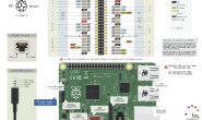
And here is the pinout of the RPi2:
将LED的负极连接到Raspberry Pi2的GPIO 5引脚(Board编号29),正极串联嗲足后连接到3.3v电源。(请务必注意极性,在直插型封装的LED中,较长的引脚是正极+,较短的引脚是负极-)

Image made with Fritzing
Here is an example of what your breadboard might look like with the circuit assembled:

Image made with Fritzing
For MinnowBoard Max (MBM)
We will connect the one end of the LED to GPIO 5 (pin 18 on the JP1
expansion header) on the MBM, the other end to the resistor, and the
resistor to the 3.3 volt power supply from the MBM.
Note that the polarity of the LED is important. Make sure the shorter
leg (-) is connected to GPIO 5 and the longer leg (+) to the resistor or
it wont light up.
And here is the JP1 connector on the MBM:

Image made with Fritzing
Here is an example of what your breadboard might look like with the circuit assembled:

Image made with Fritzing
Deploy your app
If you’re building for Minnowboard Max, select x86 in the architecture dropdown. If you’re building for Raspberry Pi 2, select ARM.
When everything is set up, you should be able to press F5 from Visual
Studio. The Blinky app will deploy and start on the Windows IoT
device, and you should see the LED blink in sync with the simulation on
the screen.
部署应用程序
对于Raspberry Pi2来说,应该在architecture的下拉菜单中选择ARM。
以上的步骤都做好了以后。可以按下F5,程序会自动运行,然后就可以看到闪烁的LED和下面的模拟界面。

Congratulations! You controlled one of the GPIO pins on your Windows IoT device.
Let’s look at the code
The code for this sample is pretty simple. We use a timer, and each
time the ‘Tick’ event is called, we flip the state of the LED.
Timer code
Here is how you set up the timer in C#:
可以通过改变滑块的位置来调整LED闪烁的有效时间
代码详解
下面就是这个程序的代码,基本工作原理是当定时器的时间达到后,调用事件Tick改变LED的状态。
定时器代码
这里是设置定时器的C#代码
public MainPage()
{
    // ...

    this.timer = new DispatcherTimer();
    this.timer.Interval = TimeSpan.FromMilliseconds(500);
    this.timer.Tick += Timer_Tick;
    this.timer.Start();

    // ...
}

private void Timer_Tick(object sender, object e)
{
    FlipLED();
}
Initialize the GPIO pin
To drive the GPIO pin, first we need to initialize it. Here is the C#
code (notice how we leverage the new WinRT classes in the
Windows.Devices.Gpio namespace):
初始化GPIO引脚
为了能够驱动GPIO,首先需要对它进行初始化,这里是初始化程序的C#代码
using Windows.Devices.Gpio;

private void InitGPIO()
{
    var gpio = GpioController.GetDefault();

    // Show an error if there is no GPIO controller
    if (gpio == null)
    {
        pin = null;
        GpioStatus.Text = "There is no GPIO controller on this device.";
        return;
    }

    pin = gpio.OpenPin(LED_PIN);

    // Show an error if the pin wasn’t initialized properly
    if (pin == null)
    {
        GpioStatus.Text = "There were problems initializing the GPIO pin.";
        return;
    }

    pin.Write(GpioPinValue.High);
    pin.SetDriveMode(GpioPinDriveMode.Output);

    GpioStatus.Text = "GPIO pin initialized correctly.";
}
Let’s break this down a little:
-
First, we use
GpioController.GetDefault()to get the GPIO controller. -
If the device does not have a GPIO controller, this function will return
null. -
Then we attempt to open the pin by calling
GpioController.OpenPin()with theLED_PINvalue. -
Once we have the
pin, we set it to be off (High) by default using theGpioPin.Write()function. -
We also set the
pinto run in output mode using theGpioPin.SetDriveMode()function.
Modify the state of the GPIO pin
Once we have access to the GpioOutputPin instance, it’s trivial to change the state of the pin to turn the LED on or off.
To turn the LED on, simply write the value GpioPinValue.Low to the pin:
this.pin.Write(GpioPinValue.Low);
and of course, write GpioPinValue.High to turn the LED off:
this.pin.Write(GpioPinValue.High);
Remember that we connected the other end of the LED to the 3.3 Volts
power supply, so we need to drive the pin to low to have current flow
into the LED.
简单的解释就是:
~首先,使用GpioController.GetDefault()获取GPIO控制权限
~如果设备不具有可用的GPIO资源,则返回null
~接下来通过调用GpioController.OpenPin()函数来打开GPIO引脚
~当我们获取了GPIO的控制权限并打开了GPIO引脚后,使用GpioPin.Write()函数来将LED关闭(参数设置High)
~这里还使用了GpioPin.SetDriveMode()函数将GPIO引脚的工作模式设置为输出模式。
改变GPIO引脚的状态
使用GpioPinValue.Low参数打开LED:
this.pin.Write(GpioPinValue.Low);
使用GpioPinValue.High参数关闭LED:
this.pin.Write(GpioPinValue.High);
因为我们将LED的正极连接到了3.3V电源,所以这里通过将GPIO引脚置低电平来打开LED。


